|
AKAI GX-280D REEL-TO-REEL TAPE DECK
|
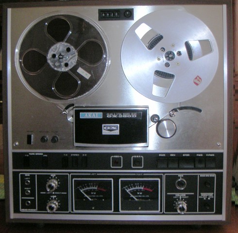
A
few years ago I bought - on ebay - an Akai GX-280D reel-to-reel tape
deck dating from the early seventies, as I had a collection of my
father's tapes of family gatherings in the fifties and sixties
that I wanted to convert to digital format.
I originally had about 17 tapes - my sister has since found another 13
- and I set about transcribing them with the Akai deck, a laptop, and
some audio recording software.
The deck had problems. It had obviously spent a lot of time with
a heavy smoker - it stank of stale smoke, and that or age had made it
electrically and mechanically touchy. It was just usable if I was
willing to watch over it while it was playing, and then tinker with it when the
mechanism would unexpectedly stop for no reason.
When the most recent 13 tapes showed up, though, I decided to fix the deck before I used it for this batch.
There were two major problems, and a couple of minor ones, plus one I
created myself when I blew two transistors in the power supply while
poking a screwdriver in the wrong place.
Playback Amplifier Fix
One of the major problems had been irrelevant for the first batch
of tapes, and still was; still I wanted to fix it. The right
playback amplifier was dead and just sat there generating noise.
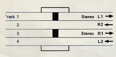
Now the tapes I had were recorded on a monaural machine which recorded
on the upper half of the 1/4 inch tape (tracks 1 and 2 in the diagram below); the Akai is a stereo deck and
the tracks are interleaved so that in the forward direction, the left
channel is recorded on the upper 1/16 inch of the tape, track 1, and the right
channel on track 3. That means that if the original monaural tape was
recorded only in the forward direction, the left pickup of the Akai
sees audio and the right pickup sees nothing, but if the original was
recorded in both directions, the right pickup should reproduce the
reverse track, reversed in time.
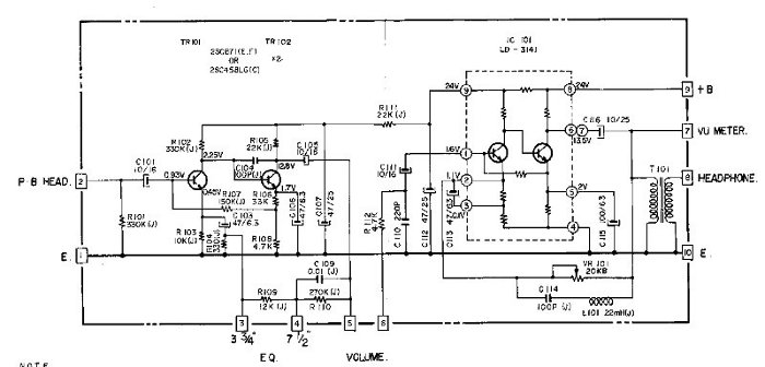
The playback
amplifier has two stages. The first is the input stage connected
directly to the playback head. This stage worked fine. The
second stage gets its input from a gain control that is connected
either to the output of the first stage or to the tape deck record
input, depending on the position of the source/tape switch. This
was where the problem was. I quickly found on the web that the
primitive IC used for gain in this stage, the LD3141, was notoriously
flaky, and was known to produce the symptoms I was seeing.
This IC (see the picture below) probably hasn't been produced in
decades, although it is available on the web as "new old stock."
I didn't want to go this route, as I figured that if I bought a
replacement IC there was no reason it wouldn't develop the same problem.
This IC is used in other Akai tape decks, and someone with a 1730D-SS has posted a fix that involves substituting an op-amp and making some circuit changes. It looks messy.
I have the schematics for my deck, and the playback amplifier schematic
shows what the LD3141 looks like inside, minus component values.
Six of the seven resistors come directly out to pins, and their values
can be measured with an ohmmeter (on the good left-channel part I had),
as they are isolated from each other by transistor junctions. The
value of the seventh resistor, the one in the collector of the input
transistor, can be deduced from the test voltages shown on the
schematic. I figured it would be easy just to build a little
board to replace the IC. As for the transistors, there was no
reason not to use the surface-mount equivalent of 2N2222A's, as noise
performance isn't critical here in the second stage of a 1970's era
tape amplifier. And 2N2222A noise perfomance isn't so bad, anyway.
 Akai playback amp schematic
Parts values here:
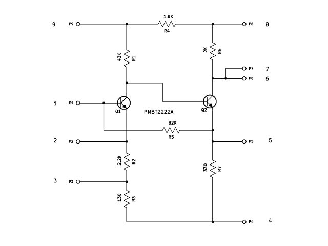 IC replacement board schematic
The board I made
isn't much bigger than the original IC. The final version has
leads soldered on, alternating front and back, mimicking the pin
configuration of the original part. Pin 1 is on the left on both
parts below, with the odd pins coming out the component side of the board and the even pins on the back side:
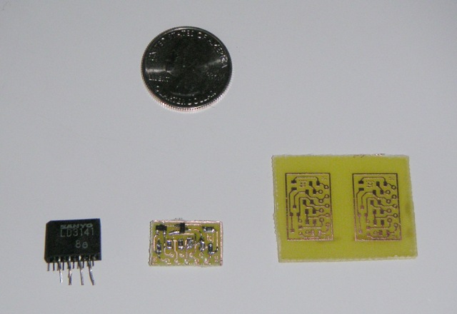 Original, replacement board, and a couple of spare bare boards
PDF of the board artwork - you should be able to duplicate this if you're willing to etch the board.
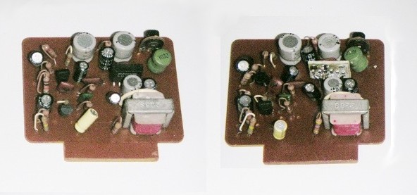
Original amp board, and board with IC replacement installed
Tape Tension Switch Fix
When
I first used the deck, the tape would stop during play for no reason
and at random times, and it would often refuse to start up again on
hitting the play button. This could happen every couple of
minutes or every few hours. Playing with the tape tension arm
(visible to the right of the capstan in the photo above) seemed to fix
this sometimes.
The tape transport control circuit is a complicated tangle of
diode-transistor-relay logic. In a few places, it depends on the
forward drop across germanium diodes being less than a silicon
transistor base-emitter forward drop. Problems with a switch that
would introduce an additional voltage drop would keep the transport
from functioning properly.
I took out the microswitch attached to the tension arm and found it
intermittently changed on-resistance depending on how far in the
plunger was pushed. It's an Omron part, V-1A44. It's not
made anymore, but the Omron VX-5-1A2 from Mouser works as a
substitute. I started out with another switch from Digikey, but
discovered that the activation force was too great (100g instead of the
roughly 25g needed here) and the tension arm wouldn't move
smoothly.
There are some other switches of this type used in the transport mechanism, so I may wind up replacing those eventually.
Other Fixes
There were three other minor problems:
1.
The capstan idler bearing squeeked. This comes off easily
and I just put a little grease on the sleeve bearing.
2.
The index counter wasn't moving at all. It turned out that it was
completely frozen, and I had to take it out and work some oil into the
sleeve bearing that its belt pulley is mounted on. Getting to it, of
course, involved disassembling some of the transport.
3. I accidentally shorted the output of the power supply (which is on the
servo board) and blew two power transistors, TR251 (a 2SC1013) and
TR252 (a 2SD234). Neither of these transistors is available any
more, but each can be replaced with a TIP31C. For the 2SC1013,
though, the pinout is C-B-E, so you have to cross over the base and collector leads to make it fit on the board.