The Simple Version
Human perception of the intensity of sensation is more or less logarithmic.
If we double brightness or loudness, we have to double it again to get
the same sense of change of intensity.
Pots used for controlling quantities that we perceive are therefore
made to match this logarithmic characteristic, and have a resistance
taper constructed so that their transfer function with respect to
rotation is exponential (even though they're referred to as 'log
pots'). But the overwhelming majority of the pots sold are
approximations - generally two- or three-segment piecewise linear
approximations. And of course, zero rotation will always
correspond to zero output, even though that can't happen with an ideally
exponential transfer function.
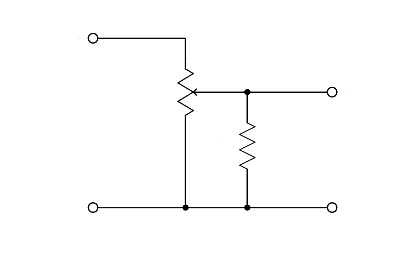
It's possible to get an approximation of log taper by
shunting the wiper to the bottom leg of a linear pot with a resistor of
roughly one-tenth the value of the pot. This is useful if a
particular model of pot is only easily available in a linear taper, or
with digital pots, which are generally 2n taps of the same resistance
value. It's also useful if a reverse taper is what's
needed. The ratio of resistor to pot value can be adjusted to
give the best fit to the desired characteristic along the segment of
the transfer curve where accuracy is most important. A possible
disadvantage of this method, though, is that the pot no longer presents
a constant load to what's driving it.
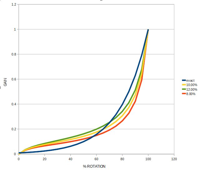
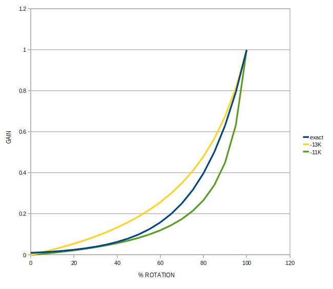
Transfer functions for the given ratio of fixed resistor value to pot value:
The plot above shows an ideally exponential transfer function (blue) ,
with the gain set to reach 10% of full value at 50% rotation, which is
typical for audio pots. The other three curves represent the
transfer functions of a linear pot shunted by 8%, 10%, and 12% of their
total resistance.
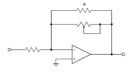
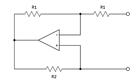
Using Negative Resistance
An interesting pseudo-logarithmic transfer function can be
derived using the the inverting op-amp configuration. Consider
first an op amp with a variable resistor as the feedback element, and
then add a fixed resistor across it:
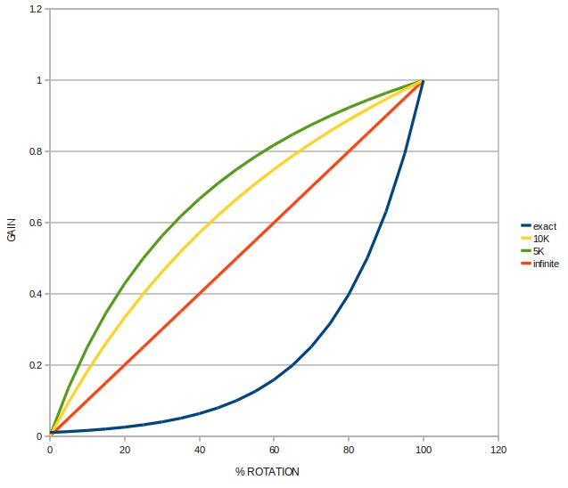
If the resistor is infinite, the resulting transfer function
(normalized gain vs pot rotation) is a straight line, but as R
decreases, the curves bow out in the wrong direction:
The plot shows various values of R paired with a 10K pot.
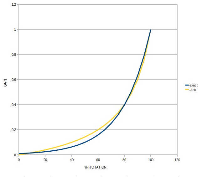
So then what happens if R becomes negative? This:
Which is pretty much what we're looking for - a reasonable
approximation of exponential that can be adjusted around the ideal
curve.
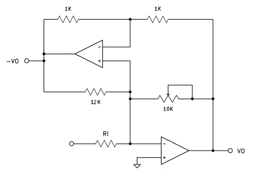
A negative resistance is just a two terminal device in which current is
proportional to voltage, but flows backwards. It can be realized with
an op-amp:
A voltage V applied to the lower terminal (relative to the upper
terminal) will be met by an opposing current coming from R2. The current is -V/R2, so
the apparent resistance is -R2. The value of R1 doesn't matter, as long as both resistors are the same.
This circuit can replace the resistor R in the original circuit above:
RI here just sets the gain for the whole stage. Note that the
input impedance of this circuit stays constant as gain is
changed. Also note that the inverse of VO is now available,
useful if this stage needs to drive a balanced load, like the input to
an audio A/D converter.
Transfer function: