This
was my first stab at a digital-out balanced-input microphone
preamp using a
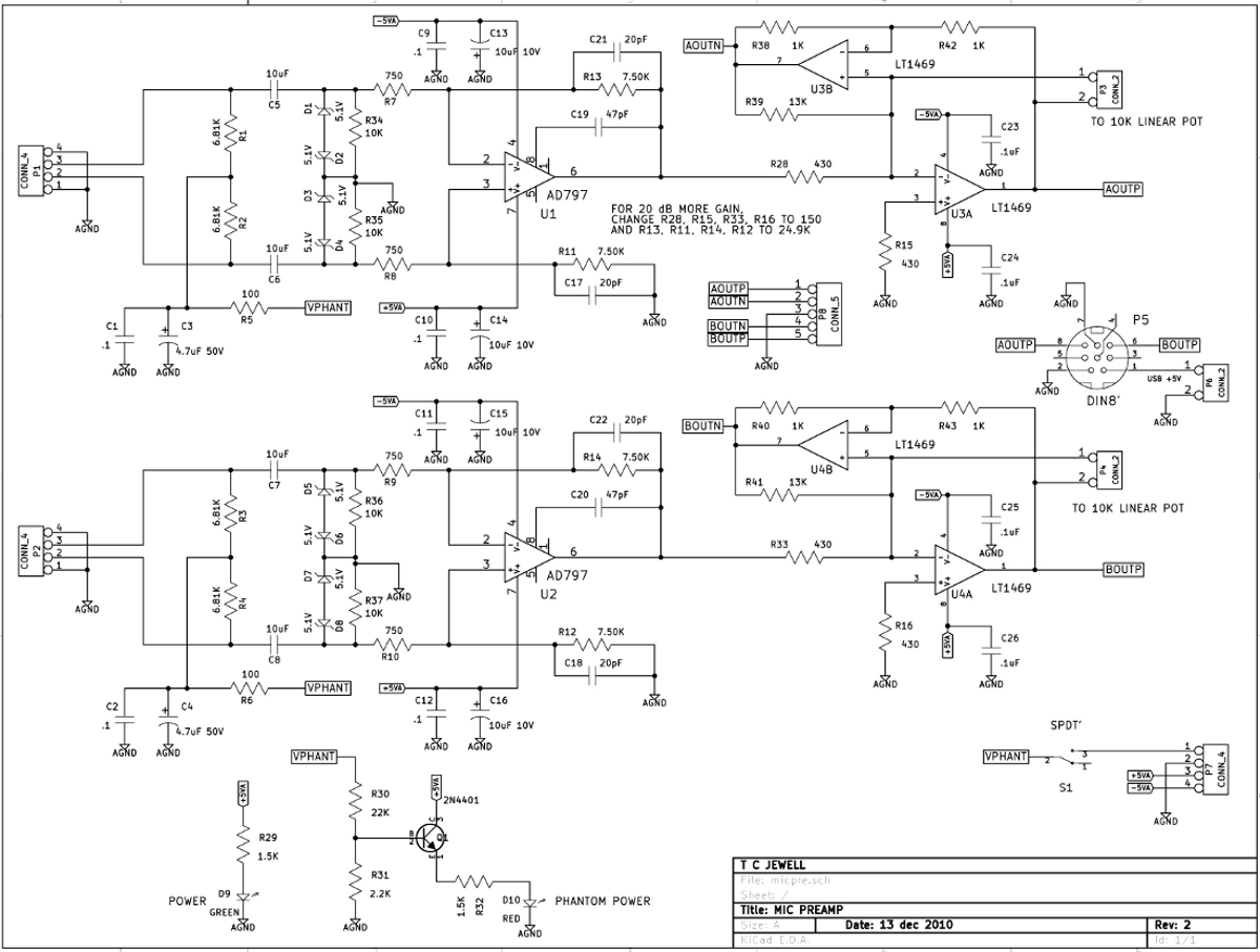
very low noise input stage op-amp, the AD797. When I started out,
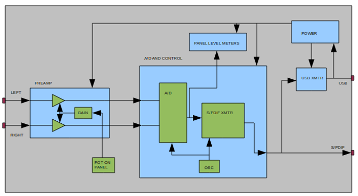
the aim was first to have a preamp with an analog output suitable for
feeding to a sound card, with a DC/DC converter that would run from 5V
and provide rail voltages for the op amps as well as phantom
power. Building my own, I could design it with no electrolytic
capacitors in the signal path. Then I would move on to providing an A/D
section and
eliminating the sound card.
The interesting part of the preamp board is the second stage, which
uses an op-amp in inverting configuration with a fed-back negative
resistance provided by another op-amp to provide pseudo-logarithmic
gain control using a linear pot. This circuit has the additional
advantage of delivering a balanced output to drive the balanced inputs of the
A/D converter.
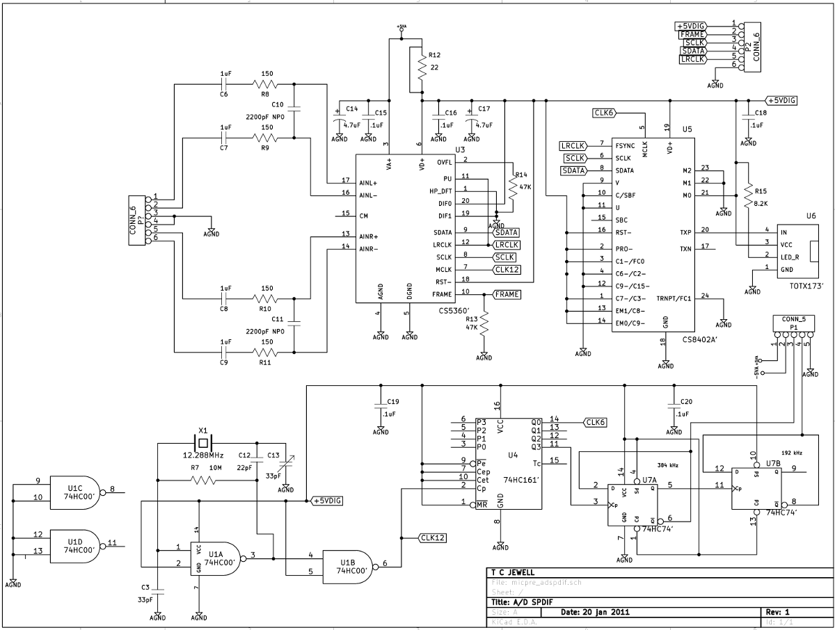
I then added an A/D converter board that used two now-obsolete
Crystal/CIrrus parts, the CS5360 24-bit A/D converter and the CS8402A
S/PDIF transmitter, with the aim of using the preamp with the optical
(TOSLINK) input of a sound card.
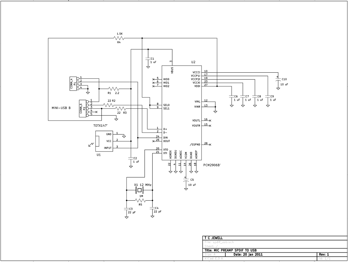
Eventually I realized that USB would be more convenient for portability
than S/PDIF, and I found TI's PC2906B 16-bit S/PDIF-to-USB converter
(that's not what they call it, but that's what I use it for).
This of course limited the output to 16 bits rather than 24, and
introduced the possibility of noise coming in through the USB
connection.
Noise coming in on the USB power line has not turned out to be a
problem. I've made comparisons between the preamp set up with USB
output, and then set up with optical S/PDIF output with an independent,
isolated power supply, and found no serious difference (neglecting
harmonics of 60 Hz coming from the independent power supply!).
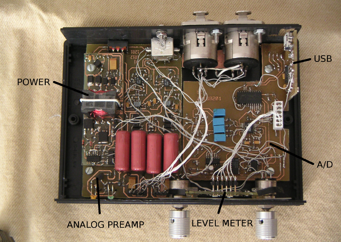
Preamp stage:
A/D and S/PDIF transmitter:
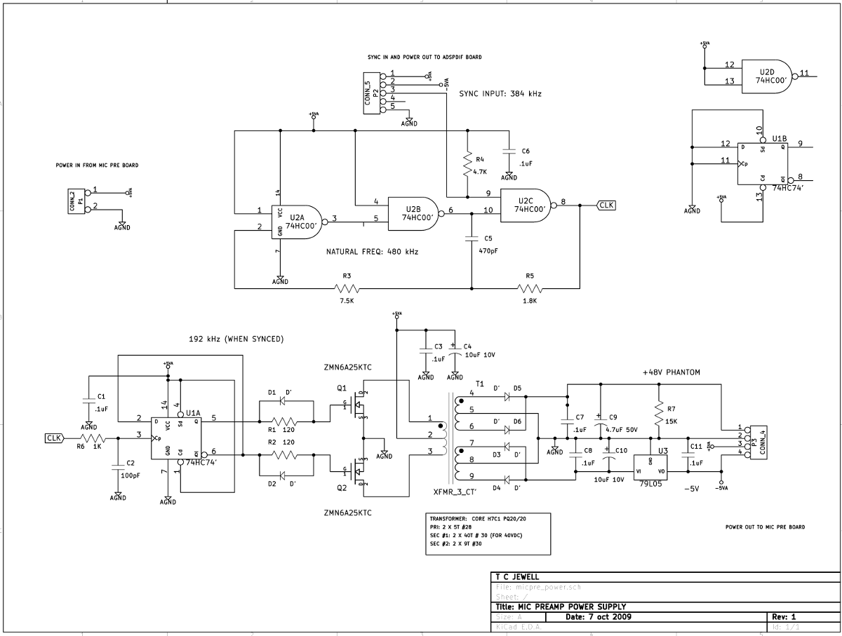
Power.
Note that the converter will free-run until it is connected to and
syncs with the master oscillator on the A/D board:
USB board - nothing much to see here:
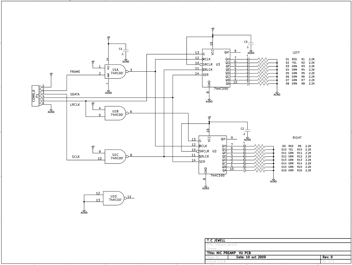
Metering board to display left and right peak level meters:
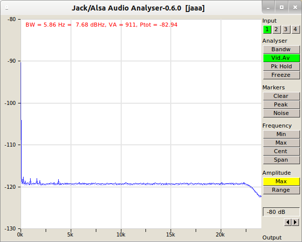
Noise spectrum with 0 gain - as the input to the A/D is essentially shorted, this is the noise floor of the CS5360 A/D:
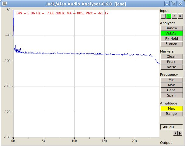
Noise
spectrum at full gain. This is the gain of the input stage, 29 dB,
plus the gain of the A/D driver stage, 55 dB, for a total of 84 dB.
In
this last plot, the noise from the AD797 input stage is
visible. The AD797 claims typical noise of .9 nV/root Hz from
about 1kHz on up. Amplified by 84 dB, this is 14 uV/root Hz going
into the A/D converter, which has a full scale input of 2 V rms.
The spectrogram above shows data analyzed at a bandwidth of 5.86 Hz,
and multiplying the 14 uV/root Hz by the square root of 5.86 Hz/1 Hz
yields 35 uV in 5.86 Hz. This is 95 dB below the 2 V rms full
scale input of the A/D, and that is what's shown in the plot
above.
With a condenser microphone, the gain is
likely to be set some 40 dB below this maximum. This puts the
noise from the input stage below the noise shown in the first plot. The
reason for
such a high gain to begin with was to accomodate a very low output
dynamic microphone. But even with a dynamic microphone, the gain
will never be set to full.